Something about the interpretation
(from Benny Rodax)
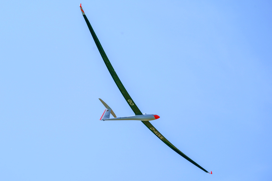
The Nimbus was actually quite an exciting project and perhaps it is interesting to report a bit on the background. When we first discussed using the latest generation of airfoils for the GPS triangle scale class in the inner wing, I had serious reservations. The idea of Pascal to realize a box-beam surface connection (as in the man-carrying ETA) as a central plugging, then only allowed an implementation with a "reasonable" structure.
Reasonable is probably not the right word for a Nimbus 4 in a scale of 1:3. This means for the model a span of 8.84m and 23.15kg maximum takeoff mass to achieve a wing loading of 115g/dm^2 - with an aspect ratio of almost 39! With this, the lift-dependent drag is already well under control, pressure and frictional drag are minimized by the airfoil tract, which is consistently trimmed for glide and climb performance. The following picture then emerges for the thickness distribution over the dimensionless half-span:
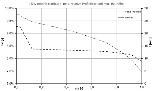
The dashed line shows the relative profile thickness on the left and the dotted line shows the resulting overall height in the area of the greatest profile thickness. So 90% of the halfspan is below 8.5% airfoil thickness and only in the area of the wing root a maximum overall height of more than 25mm is reached. This is really, really not much and definitely requires the pilot to maintain certain operating limits. The "full-throttle stability" often quoted in this forum is not given here! The spar structure is designed for the following flight range:
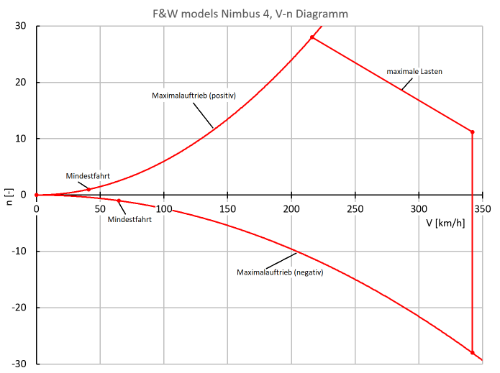
Above the airspeed, the maximum positive load multiples (normal flight) and maximum negative load multiples (inverted flight) are shown here. Within the red limits, the aircraft can be moved - always provided that the technology works properly and the structure and all linkages are not damaged. The positive parabola results from the maximum lift, above the minimum speed the plane can just reach the single load multiple and flies. At slightly above 200km/h the maneuvering speed is reached. By pulling the elevator fully, the maximum load for which the structure is designed can be reached. This corresponds to a load multiple of n=28. If you now want to fly even faster, you can do so - but the maximum load multiples that can be tolerated will then drop to n=11 at 340km/h. Personally, I would recommend to avoid the speed range above 250km/h to always have reserves in gusty weather and to keep the risk of rudder flutter low. At negative load multiples, the plane virtually limits itself by a relatively small negative lift coefficient. Aerobatics were not on the wish list here either.
Now, of course, it is still interesting to know how much the wing approximately deflects under load. It looks something like this:
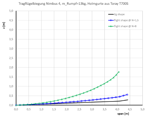
The undeformed wing front view is shown in black, blue under a load multiple of n=1.5, green corresponds to n=8. Thus, when thermalling with n=1.5, one approximately doubles the V-position. I have considered this effect e.g. in the flight mechanics calculations. The case with n=8 corresponds to the sharpest turn at the GPS triangle, above n~8 the GPS receivers typically drop out for a short time.
Besides the aerodynamic and flight mechanical design, the structure was a major task in this project. At this point I would like to thank Jojo and Steffen for checking the plausibility of my calculations. I wish all future Nimbus pilots a lot of fun and great flights with this crazy airplane!
Reactions: LimaBravo, NakedZ, DG1000Matze and 7 more (www.rc-network.de)
Interpretation: www.rc-network.de/forum

